Your LEGO city has grown beyond a simple grid of straight streets. You’ve mastered the basics of standard brick building techniques, and now you’re ready to add the organic flow of real urban infrastructure—sweeping curves that guide the eye, hills that add dramatic elevation changes, and roads that feel engineered rather than merely placed.
Advanced road construction separates casual city builders from serious urban planners. While straight roads on flat baseplates work for basic layouts, creating believable infrastructure requires mastering techniques that challenge both your engineering skills and creative vision. This guide walks through the methods AFOLs use to build roads that look like they belong in actual cities, not just on display shelves.
Understanding Road Construction Fundamentals
Before diving into advanced techniques, let’s establish what makes LEGO road building complex. Unlike structures that sit stationary, roads need to support vehicle play, connect seamlessly to buildings, and maintain visual consistency across your entire city layout.
The challenge intensifies when you move beyond straight sections. Real roads rarely run in perfect lines—they curve around obstacles, climb hills, and adapt to terrain. Replicating this in LEGO requires understanding how to manipulate plates and bricks in ways that seem impossible at first glance.
Most advanced road techniques share common principles: they use offset attachment points to create angles, they distribute stress across multiple connection points for stability, and they employ techniques from both SNOT building and traditional stacking methods. Your roads become three-dimensional engineering projects rather than simple tile surfaces.
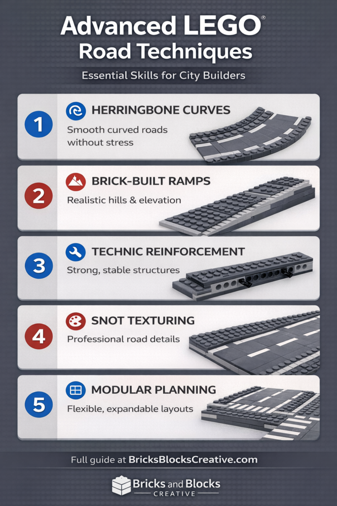
Creating Smooth Curved Roads
Curved roads present the first major challenge in advanced city building. LEGO’s grid-based system naturally wants to create 90-degree angles, but believable roads need gentle arcs that vehicles can navigate smoothly.
The Segmented Herringbone Method
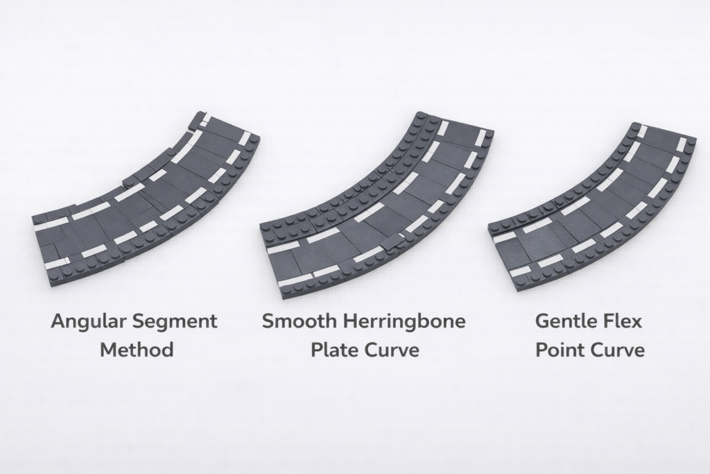
The herringbone plate curve technique transforms rigid LEGO plates into flowing curves by exploiting tiny gaps between offset plates. You create the curve by staggering 2-stud-wide plate strips so each strip rotates slightly relative to the one beneath it. Rather than forcing bricks to bend—which stresses the plastic and creates visible gaps—this method produces natural curves through accumulated small rotations.
Start with a base layer of standard plates arranged in your general curve path. Build upward using 2×4 or 2×6 plates, but offset each new plate by one stud compared to the layer below. The offset creates tiny pivot points where plates don’t fully overlap. When you add enough layers, these small pivots compound into a visible curve without putting stress on any individual connection.
The beauty of this technique is its adjustability. Tighter curves require more aggressive offsets between layers, while gentle highway curves need only minimal stagger. You can build the entire road structure, test the curve, then partially disassemble and adjust if the radius isn’t quite right. This iterative approach lets you dial in exactly the curve your city plan requires.
For a 16-stud-wide road, build the central 8 studs as interlocking 2×4 plate “spines” in the herringbone pattern, then add straight outer sections for curbs and sidewalks. The curved center guides the overall road shape while the rigid edges maintain clean borders with your buildings and landscaping.
Triangle and Segment Wedging
Another proven approach builds curves from repeated wedge or triangular modules that step outward incrementally. Each module adds a small angle change—perhaps 5-10 degrees—which reads as a smooth curve when viewed at city scale. This modular method offers significant advantages for large cities because you can build standardized curved sections that connect to straight road segments at predetermined angles.
Think of it like building with Technic gears versus System bricks. Each wedge module acts like a gear tooth, advancing the curve by a fixed amount. Build enough modules in sequence and you create a quarter-circle, an S-curve, or any other arc your street plan demands.
The technique requires careful planning. Before building, sketch your desired curve and divide it into equal angle segments—typically 6-12 segments for a 90-degree turn. Each segment becomes one wedge module. Build your first module with the appropriate angle, then duplicate it exactly for the remaining segments. Consistency is crucial; even small variations in module angles create visible wobbles in the finished curve.
Lock the modules together using plates that span across joints, essentially creating a structural spine underneath your decorative road surface. This hidden reinforcement prevents segments from separating during handling while keeping the top surface clean for tiling.
Flex Points for Organic Curves
Sometimes you don’t need a precise radius—you just want a gentle, organic curve that avoids the rigid feel of angled segments. The flex point technique achieves this by intentionally leaving small gaps or “wiggle room” between tiled plate strips, allowing the road to flex into a gentle arc without stressing parts.
Build your road base as usual, but when tiling the surface, leave 1-2 plate widths between adjacent tile strips rather than placing them tightly together. These gaps create flex points. When you place the road on your baseplate and gently curve it to match your desired arc, the gaps close slightly on the inside of the curve and open slightly on the outside, accommodating the bend.
The key is balancing flexibility with structural integrity. Too many gaps and your road becomes floppy and unstable. Too few and you eliminate the flex that allows curves. A good starting point: place flex gaps every 6-8 studs along the road length. Test the curve, then adjust gap frequency until you achieve the right balance of flexibility and stability.
This technique works best for subtle curves over long distances—think gentle highway arcs or roads that curve around hillsides. For tight urban corners, the segment or herringbone methods provide better control.
Modern Road Plate Adaptations
LEGO’s official road plate system has evolved to include specialized curved sections, but creative builders extend these possibilities by modifying standard plates. The trick involves widening the plate area and using angled tiles or plates at 45 degrees to create diagonal edges that read as curves when combined.
Start with a straight road plate section. Add 2×2 or 2×4 plates at each corner, positioned at 45-degree angles to the main plate. Top these with angled tiles that match your road color. When you connect multiple modified sections, the 45-degree corners create an octagonal approximation of a curve—not perfectly smooth, but convincingly curved when viewed in the context of a larger city.
This method integrates seamlessly with official LEGO road plates if you’re expanding an existing city, while giving you curve options beyond what’s available in retail sets. It’s also reversible; you can modify plates for a specific layout, then return them to standard configuration if your city plan changes.
🌀 Road Curve Calculator
Plan perfect curved LEGO roads with precision
—
Building Sloped Streets and Hills
Elevation changes transform flat cities into dynamic urban landscapes. Hills add visual interest, create opportunities for dramatic architecture, and challenge your engineering skills in ways flat building never does.
Brick-Built Ramps vs. Tilting Baseplates
The fundamental choice in sloped road construction is between tilting entire baseplates or building ramps brick-by-brick underneath your road surface. Tilting baseplates seems easier initially—just prop one edge up and you have an instant hill. But this approach creates problems. Tilted baseplates don't connect cleanly to flat sections, they limit your ability to modify the slope later, and they make your entire city less modular.
Brick-built ramps keep your city modular and adjustable. Build the slope by stacking bricks and plates underneath a tiled surface, creating a road that remains removable and reconfigurable. The ramp becomes part of your city's architecture rather than a permanent fixture.
Experienced city builders favor gradual slopes over steep ramps. A good rule of thumb: rise roughly 20 bricks over 3.5 baseplates (about 112 studs) of horizontal distance. This creates a realistic grade that vehicles can believably climb while maintaining structural stability. Steeper slopes look dramatic but create engineering headaches—vehicles slide, the structure becomes unstable, and the visual scale feels wrong.
Wedge Plates and Smooth Transitions
Where sloped roads meet rockwork, retaining walls, or landscape elements, wedge plates create seamless visual transitions. Standard LEGO wedges come in various angles, and choosing the right angle to match your road's slope eliminates the stepped, Lego-y look of exposed brick layers.
Build your road's supporting structure first—the brick-built ramp described above. Then study the angle. If you've built a gradual slope using the 20-bricks-over-3.5-baseplates guideline, you'll need relatively shallow wedge plates. Check your collection for 2×2, 2×3, or 2×4 wedges that approximate this angle, then position them along the edges where your road meets terrain.
The wedge plates don't carry structural load—that's handled by your brick-built ramp. They're purely aesthetic, smoothing the visual transition and hiding the stepped brick layers underneath. This separation of structural and decorative elements is a hallmark of advanced LEGO construction.
Integrated Sidewalks on Slopes
Sidewalks complicate sloped roads because they need to rise with the road while maintaining clean borders and avoiding awkward gaps. Keep sidewalks one tile higher than the road surface using additional plates, creating a subtle curb. Where the slope changes grade, step or terrace the sidewalk rather than trying to maintain a continuous slope.
Think of this like real civil engineering. Actual sidewalks on steep hills often include terraced sections or small steps to prevent them from becoming too steep for pedestrians. Replicating this in LEGO creates both visual realism and structural advantages—the terraced sections provide natural spots to lock sidewalk elements into your supporting structure.
Build sidewalks as separate assemblies that attach to the main road structure at regular intervals. This modular approach lets you adjust sidewalk height and position independently of the road surface, critical for getting the proportions right on complex slopes.
Layered Support Systems
The hidden support structure underneath sloped roads determines whether your build remains stable or collapses under its own weight. Stack 2×N bricks in staggered fashion under the ramp, similar to how real concrete forms support poured roadways. Occasionally turn bricks sideways to create internal "shelves" that distribute weight and prevent sagging.
Advanced builders also use the Technic beam technique here, running long Technic bricks through the support structure as hidden reinforcement girders. Pin these beams together with Technic pins, creating a rigid spine that prevents the entire ramp from bowing or separating under stress.
The support structure should touch the road surface at regular intervals—every 6-8 studs works well. These contact points transfer the road's weight into the supporting structure, while the spaces between them reduce part count and allow for integration of other elements like drainage features or underground utilities.
⛰️ Slope Grade Calculator
Check if your LEGO road slope is stable
Maintaining Structural Stability on Inclines
Sloped roads want to slide apart, twist under stress, or develop weak points at angle transitions. Understanding how to prevent these failures separates functional builds from display-only models.
Technic Spine Reinforcement
Long sloped roads benefit enormously from Technic spine reinforcement—essentially creating a hidden girder system using Technic bricks pinned together underneath the decorative road surface. Build the spine first using 1×6 or longer Technic bricks connected end-to-end with Technic pins. This creates a rigid beam that resists bending and twisting.
Attach your road surface elements to this spine at regular intervals. The spine carries the structural load while surface elements handle aesthetics. This separation lets you use fragile or decorative parts on the visible surface without compromising stability.
When building the Technic spine, alternate brick orientation—run some bricks parallel to the road direction, others perpendicular. This creates a lattice effect that resists twisting forces from multiple directions. Think of it as the difference between a single beam and a truss bridge; the lattice distributes forces more effectively than a simple linear spine.
Side-Wall Bracing
Sloped roads running between cliffs, buildings, or retaining walls gain significant stability from side-wall bracing. Rather than having the road float in space supported only from below, integrate it with adjacent structures using bricks rotated 90 degrees that protrude under the road as brackets.
The concept mirrors real civil engineering. Actual cliffside roads often include support structures built into the rock face or retaining walls. Your LEGO version creates brackets by building 1×2 or 1×4 bricks into cliff walls, oriented perpendicular to the wall face. These brackets extend under the road edge, creating ledges on which the road rests.
This technique requires simultaneous construction of both road and adjacent structures. You can't add effective side-wall bracing after completing the road—the connections need to interlock from the beginning. Plan your road path and adjacent structures together as an integrated system.
Overlapping Brick Courses
A deceptively simple but essential technique: run continuous layers of overlapping bricks across the top of your stacked road supports. This ties multiple support columns into one stable mass, preventing individual columns from shifting or toppling.
Each overlapping course should span at least two support columns, creating redundant connections throughout the structure. If one connection point loosens slightly through handling, neighboring connections maintain stability. This redundancy is crucial for playable cities versus static displays.
The overlapping courses also distribute point loads. When you place a heavy LEGO vehicle on your sloped road, its weight presses down on specific spots. The overlapping courses spread this force across multiple support points rather than stressing a single column.
SNOT Techniques for Load-Bearing Structures
Advanced SNOT construction can rival Technic for strength when plates and brackets are locked from multiple directions. Official LEGO sets demonstrate this in builds like large helmets or mechs, where SNOT cores with panels locked in from all sides handle significant stress.
For roads, SNOT provides anti-shear connections that prevent sloped sections from sliding downhill. Build SNOT bricks and brackets to connect the sloped road to perpendicular walls or support structures. These sideways connections resist the gravitational force trying to pull your road apart, essentially wedging the structure in place.
The technique requires thoughtful part selection. Standard 1×2 SNOT bricks (headlight bricks) work well for light-duty connections, but heavy roads need the stronger grip of bracket pieces or modified plates with side studs. Test connections by applying gentle pressure in the direction gravity would pull; if anything shifts, reinforce with additional SNOT connections or rethink your attachment strategy.
SNOT Techniques for Road Textures and Markings
The decorative surface of your roads—texture, lane markings, drainage features—benefits enormously from Studs Not On Top techniques. SNOT lets you achieve details impossible with traditional building methods.
Creating Ultra-Thin Lane Lines
Standard LEGO building creates lane markings by placing white or yellow tiles on a gray road surface. This works, but the tiles are one plate thick, creating slightly raised markings that look oversized at minifigure scale. SNOT techniques produce crisp, continuous stripes that read as painted lines rather than built elements.
Build the road surface sideways using SNOT bricks so the driving surface is actually the side of plates or bricks. Attach thin white or yellow tiles via brackets or headlight bricks positioned at half-stud offsets. The result: lane markings that appear almost flush with the road surface, with thickness measured in fractions of a plate rather than full plate heights.
Advanced builders use this for arrow markings, crosswalks, and parking space lines. Build the marking from cheese slopes or tiles mounted on clips and bars—similar to official LEGO train striping techniques but adapted for roads. The three-dimensional nature of SNOT mounting lets you create markings at any angle, not just aligned to the building grid.
Subtle Texture Variations
Real roads show wear, patching, drainage channels, and material changes. SNOT mounting of grille tiles, jumper plates, or 1×1 tiles sideways simulates these details convincingly. Mount grille tiles at slight angles for drainage grates, use dark gray 1×1 tiles to represent patched asphalt, or position textured plates to show tire wear paths.
The technique works because it breaks free from the LEGO grid. Traditional building forces everything to align to stud positions, creating unnaturally regular patterns. SNOT mounting lets you position texture elements at odd angles and spacing, mimicking the irregular nature of real road surfaces.
For city builders interested in creating realistic displays, this level of texture detail separates amateur builds from professional-quality work. The textures don't need to be obvious—subtle variations in surface treatment create visual interest that viewers might not consciously notice but which elevates overall realism.
Quarter-Plate Offsets for Micro-Gradients
Jumper plates—those 1×2 modified plates with a single centered stud—enable quarter-plate offsets. This sounds technical, but it's transformative for road building. Real roads include subtle camber (crown) for drainage, gentle grades that help water runoff, and micro-transitions at intersections. Quarter-plate offsets let you replicate these details.
Build a section of road surface on jumper plates, and that section sits one-quarter plate higher than sections built on standard plates. String together sections at different quarter-plate heights and you create an almost imperceptible slope—exactly what you need for realistic drainage grades or the subtle rise at intersection approaches.
The technique requires patience. You're working with differences of less than a millimeter, invisible unless you sight down the road surface or place a straightedge across it. But the cumulative effect—especially in well-lit photography—adds a layer of realism that builders notice even if they can't articulate exactly what looks "right."
Trapping Loose Elements
High-level SNOT builders sometimes trap plates or panels between fixed elements so they're held in place without studs, allowing geometries that normal connections can't achieve. For roads, this enables curved gutters, irregular drainage patterns, or realistic road camber.
The technique works like this: build a rigid frame from standard bricks, leaving a gap where you want the decorative element. Insert a plate or panel into the gap without attaching it via studs—it's simply pressed between two fixed elements. Add the next layer of your structure, which locks the trapped piece in place by pressing it from above and below.
Trapped elements can be positioned at odd angles or curves impossible with studded connections. A curved gutter might use a long, thin plate bent slightly and trapped between straight road edge elements. The plate holds its curve because it's compressed from both sides, not because it's studded in place.
This is advanced technique requiring precise planning—you need to build the trapping structure, insert elements, and complete the locking mechanism in sequence. Mistakes mean partial disassembly. But the results achieve geometry literally impossible with traditional building methods, making it worthwhile for showcase roads in your LEGO city master plan.
Practical Applications and Examples
Theory transforms into practice when you apply these techniques to actual road sections. Here are proven combinations that solve common city building challenges.
The Hillside Connector Road
Problem: You need a road connecting a valley-floor commercial district to a hilltop residential neighborhood. The elevation change is about 30 plates (about 10 bricks) over a distance of 3 baseplates.
Solution: Build a brick-built ramp using the layered support system described earlier, rising gradually over the 3-baseplate distance. Use Technic spine reinforcement running the full length. Where the road curves around the hillside, apply the segmented herringbone method to create the curve while maintaining the slope. Add side-wall bracing by building the hill terrain and road simultaneously, creating brackets from the hillside that support the road edge.
For the road surface, use SNOT-mounted lane markings to create crisp center lines and edge stripes. At the steepest section, add SNOT-mounted grille tiles as drainage grates, suggesting the civil engineering required for steep road sections.
The Downtown Curve
Problem: Your city grid needs organic flow, but all your existing roads run at 90-degree angles to each other. You want to add a sweeping curve that guides traffic around a central plaza or park.
Solution: Use the triangle and segment wedging technique to create a smooth 90-degree curve. Build 8-10 identical wedge modules, each representing about 10 degrees of the turn. Connect them using overlapping plates underneath that create a structural spine. Where the curve meets existing straight roads, design the wedge modules with straight extensions that mate cleanly to your grid.
Surface the curved road with traditional tiled surface on top, but add SNOT-mounted lane markings that follow the curve smoothly. The contrast between the standard studs-up surface and the smoothly curving markings creates visual interest while maintaining structural simplicity.
The Terraced Mountain Road
Problem: Your city includes a dramatic mountain built for display purposes, and you want a winding road that switchbacks up the mountainside like real alpine roads.
Solution: Plan the road path to include several 180-degree switchback turns. Build each switchback as a separate module using the triangle segment method for the curves. Stack these modules vertically, connecting them with short straight sections that provide the elevation transition.
Use extensive side-wall bracing, building the road directly into the mountain structure—the road and mountain become one integrated build rather than separate elements. For the sharpest curves, use the herringbone method to get the tightest possible radius. Add SNOT-mounted guard rails using cheese slopes on clips, creating the protective barriers essential for mountain roads.
The Textured Urban Street
Problem: You want your downtown commercial street to show the wear and character of a decades-old urban road—patching, different surface treatments, and visible infrastructure like drainage.
Solution: Build a standard straight road section using traditional methods, but surface it with complex SNOT texturing. Use the primary road color (dark bluish gray) for most of the surface, but add sections of regular gray to represent patches. Mount grille tiles at regular intervals as drainage grates. Use SNOT-mounted jumper plates to create quarter-plate height variations suggesting subsidence around those grates.
Add crosswalks using SNOT-mounted white tiles creating thick stripes. For parking space markings, use yellow cheese slopes on clips positioned to create angled parking indicators. The result: a road that tells a story about its history and use rather than looking freshly paved.
Integration with Your City Planning
Roads don't exist in isolation—they're infrastructure connecting your city's components. Consider how road techniques integrate with your broader building strategy.
Modular Road Sections
Build roads as standardized modules that connect to each other via common connection points. A straight section might be 32 studs long (one baseplate), while curve sections span specific angles (30 degrees, 45 degrees, 90 degrees). This modular approach, similar to systematic city planning, lets you reconfigure your city layout without rebuilding roads from scratch.
Design modules with connection tabs or recessed areas that mate with adjacent modules. Include Technic pin connections in the support structure underneath so modules lock together firmly. This creates roads that you can disassemble, rearrange, and reassemble as your city evolves.
Road Width Standards
Establish standard road widths for different city areas. Residential streets might be 12 studs wide (enough for two minifig vehicles), main streets 16 studs, highways 24 studs or more. Consistency in width simplifies module building—you design your curved section once for each width, then duplicate it as needed throughout the city.
Standard widths also help with building integration. When structures know roads will always be 16 studs wide, you can design building fronts to align perfectly with road edges. This attention to systematic planning shows in the professional appearance of the finished city.
Elevation Strategy
Plan your city's elevation changes deliberately rather than randomly. Perhaps the commercial district sits at sea level (on baseplates), residential areas climb 10 plates up a gentle slope, and industrial zones sit 20 plates high on a plateau. This creates distinct visual zones while giving you specific targets for your sloped road construction.
Document elevation standards just like road widths. When you know the commercial-to-residential transition requires a 10-plate rise, you can design and build standardized connector roads that handle exactly this elevation change, making expansion consistent and modular.
Common Pitfalls and Solutions
Even experienced builders encounter specific challenges with advanced road techniques. Here's how to avoid or solve the most frequent issues.
Sagging Long Slopes
Long sloped roads tend to sag in the middle under their own weight, creating a visible dip. The solution is more frequent support points. Rather than supporting the road every 8-10 studs, increase frequency to every 4-6 studs on long slopes. Add a central Technic spine running the full road length, not just the lower support structure. Use double-height bricks in the support structure to increase rigidity.
Curves That Look Angular
Curves built with too few segments or insufficient offset look angular and artificial. Increase segment count—a 90-degree curve needs at least 8-10 segments to read as smooth at typical viewing distance. Alternatively, switch from the segment method to the herringbone method, which creates genuinely smooth curves rather than approximations.
Unstable Sloped Transitions
Roads that transition from flat to sloped often develop weak points at the transition. Reinforce these zones with overlapping brick courses that span both the flat and sloped sections. Add SNOT connections perpendicular to the road direction, creating anti-shear resistance. Build the transition zone with one extra layer of bricks for additional rigidity.
Part Stress in Tight Curves
Forcing standard plates into tight curves can stress the plastic, leading to deformation or even cracks. Never force bricks to bend beyond their natural flexibility. If your curve requires more flex than parts naturally allow, redesign using smaller segment modules or the triangle wedging method. Consider that the minimum curve radius for most LEGO elements is about 16-20 studs—tighter curves need specialized techniques or acceptance that they'll always look slightly angular.
Advanced Topics for Expert Builders
Once you've mastered fundamental curved and sloped road construction, these advanced topics add the final layer of sophistication.
Variable-Width Roads
Real roads widen for turn lanes, narrow in historic districts, and add shoulders on highways. Replicate this by building roads with variable width, expanding and contracting as needed. This requires careful planning—changes in width must taper smoothly rather than stepping abruptly. Build tapers over at least 16-24 studs of road length, adding or removing one stud of width every 4-6 studs.
Multi-Level Intersections
Urban highways include overpasses, cloverleaf interchanges, and multi-level crossings. These complex structures combine everything you've learned—curves, slopes, structural reinforcement, and SNOT detailing. Start simple with a single overpass, then progress to more complex exchanges as your skill develops. Study real highway interchange designs for inspiration, then adapt the geometry to LEGO grid constraints.
Suspension Bridges and Elevated Roads
Roads that leave the ground entirely—suspension bridges, elevated highways, futuristic skyways—require additional engineering considerations. The support structure becomes visible rather than hidden, demanding attention to aesthetics as well as function. Study advanced building techniques for creating strong, attractive support columns and cable systems.
Integrated Utilities
Real roads conceal utilities—sewers, water mains, electrical conduits. Advanced builders include these details underneath road surfaces, visible when roads are removed or in cutaway display sections. Use Technic pieces for pipes, colored 1×2 plates for electrical conduits, and build access hatches into road surfaces that lift away to reveal infrastructure beneath.
Tools and Planning Resources
Successful advanced road building requires more than technique—you need planning tools and reference materials.
Digital Design Software
Stud.io and other LEGO CAD programs let you design roads virtually before committing parts. This is especially valuable for complex curves or multi-level intersections where mistakes waste significant building time. Design in software, test the structure, then build with confidence knowing the technique works.
Virtual design also helps with part inventory planning. Complex roads consume specific pieces—brackets, SNOT bricks, Technic beams, wedge plates. Designing digitally lets you generate parts lists before starting, avoiding mid-build parts shortages.
Reference Photography
Study real roads in your area or online. Notice how curves are engineered, how drainage features appear, how lane markings handle complex intersections. This real-world reference informs your LEGO building decisions, suggesting realistic details and proportions that pure imagination might miss.
Photography also reveals how roads relate to surrounding architecture—setbacks, curbs, sidewalk widths, landscaping buffers. Incorporating these relationships makes your LEGO roads feel integrated into their environment rather than merely placed on top of baseplates.
Community Resources
The AFOL community shares advanced road building techniques through online forums, social media, and building communities. Study builds by accomplished city builders, noting how they solve specific engineering challenges. Many builders freely share techniques, part lists, and construction tips that accelerate your learning curve.
Convention displays and local LUG meetings provide hands-on study opportunities. Examining professional-quality roads in person reveals construction details invisible in photographs—how modules connect, how hidden support structures work, how SNOT techniques create specific effects.
Bringing It All Together
Advanced LEGO road building transforms your city from a collection of buildings into an integrated urban landscape. The techniques in this guide—curved construction methods, sloped road engineering, structural reinforcement strategies, and SNOT detailing—provide the tools you need to create infrastructure worthy of your architectural vision.
Start with a single curved section or a simple sloped connector between two elevation levels. Master the basic technique, then add complexity—combine curves with slopes, integrate SNOT texturing, build multi-level intersections. Each successful project builds your skill and expands what's possible in your city.
Remember that real cities evolved over decades, with infrastructure adapting to topography, economic needs, and engineering innovations. Your LEGO city can tell similar stories through thoughtful road design. A winding mountain road suggests historical growth patterns. A modern highway interchange demonstrates contemporary planning. Textured urban streets show the accumulated character of established neighborhoods.
The roads you build become more than connections between structures—they're architectural elements in their own right, worthy of the same attention to technique, detail, and realism you apply to your buildings. They prove that in LEGO city building, the spaces between buildings matter just as much as the buildings themselves.
Want to expand your LEGO city building skills? Explore our comprehensive guide to planning your LEGO city from the ground up, learn about creating effective street layouts, or discover advanced building techniques that elevate every aspect of your city construction.